For the flame radiation analysis, a well approved integral procedure in the respective spectrum is carried out with the compact flame controller. After a pre-amplification, the unwanted continuous wave light component is withdrawn from the output signal of the wear-resistant detector. The subsequent sensitiveness attitude allows an attenuation of the signal for adaptation to the combustion process. The post-connected band pass filter caused, that only the typical modulation of the flame radiation of the primary combustion zone is valued and so extraneous light signals by neighboring burners can be distinguished from its own flame. Further functional groups include signal conditioning the dynamic monitoring channel which checks the fail safe function of the device continuously.
A component or component defect leads to an immediate disconnection of the flame relay, which output is available as a floating change-over contact for use with the burner management system. The switching condition is announced additionally by a yellow LED on the reverse side of the device behind the Perspex pane. For the optimal adjustment of the compact flame controller the flame strength can be read off directly on the device by means of a pulsating green LED. For the visualization or remote indication, a current output is available at 0 or 4-20 mA. The safety switch-off time which depends on the combustibles to be checked is set ex-works to a second. Longer switch-off times are available upon request.
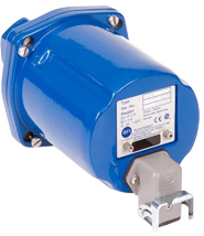
BFI’s compact flame controllers come in different models each offering slightly different features but the same technical specifications.
Technical Specifications
Spectral sensitivity
UV 280-420 nm (for natural gas, oil and mixed fire) UV1 190 to 550 nm (for natural gas, oil and mixed fire) IR 300-1050 nm (for oil and coal dust monitoring also mixed burners) IR1 1050-2700 nm (for gas flame on surface burners and heating operations again) IR2 300-2700 nm (for selective monitoring of gas and oil burner)
Optics
Opening angle 2.7°
Connection reading
Power supply 24 V DC Current consumption 100 mA
Surroundings
Ambient temperature -20°C … + 70°C
Outputs
Flame Relay 1 changeover contact, potential free VDE 0110, class A Max. 48 V switching voltage Max. 1 A Switching power (fused with 0.5 A) Max. 30 W Switching capacity Current output 0 (4) … 20 mA (Ra <250 Ohm) Error output 24 V DC short-circuit proof
Setting
Programming IRDA / USB Switching thresholds programmable via software CFC COM Power windows can be changed via software Safety switched Factory set at 1s
Mechanical connection
Sighting tube connection 1 “female thread ISO 228 Purging air 1/2 “internal thread to ISO 228 Air flow 10 m3 / h at standard conditions
Electrical connection
Standard Harting connectors HAN8 90° Ex-Housing 3m firmly connected cable OE converter Harting connectors HAN8 90° Ex-OE converter M20 gland and terminals in the interior
Housing Dimensions
Standard with flange 235 x 108 mm (length x diameter) Ex enclosures 223 x 120 mm (length x diameter) * OE converter housing 120 x 122 x 80 mm (length x width x height) * Ex-OE converter housing 232 x 232 x 166.5 mm (length x width x height) *
- without connections and mounting bracket
Housing (protection class and ATEX)
Protection standard housing and OE converter housing IP 65 ATEX Zone 2 II 3G Ex nA IIC T4 Gc X Ex-housing IP 66 ATEX Zone 1 (see declaration of conformity of housing manufacturer) Ex-OE converter housing ATEX Zone 1 (see declaration of conformity of housing manufacturer) Construction According to protection class III SELV
Weight
Standard 1.5 kg Ex-housing 4.0 kg OE converter housing 1.5 kg Ex-OE converter housing 7.0 kg
Application example
- Power Plants
- Gas turbines
- Sulfur recovery (Claus process)
- Surface burner
- Rotary kilns
- Fluidised bed combustion
- Furnaces
- High-pressure systems
- Low NOx applications