
3 Nov 2026
In-Situ Tail Gas Analysis in Sulphur Recovery Units
A Claus sulphur recovery unit (SRU) turns hydrogen sulphide into elemental sulphur. The H₂S comes from the acid gas of oil refining, natural gas processing and coke oven gas treatment. How much sulphur the unit recovers depends on one ratio: the tail gas should hold about two parts H₂S to one part SO₂. With too little combustion air, H₂S is left over; with too much, SO₂ rises. Either way, recovery falls and more sulphur goes on to the tail gas treatment unit or the incinerator.
Measuring the tail gas
The standard way to keep the ratio on target is to measure H₂S and SO₂ continuously in the tail gas leaving the last sulphur condenser, and use the result to trim the air demand of the reaction furnace. Many plants control on [H₂S] − 2[SO₂], which is zero when the ratio is exactly right.
Extractive analysers struggle here. Sulphur condenses in sample probes, heated lines and filters, so they block and need frequent cleaning.
In-situ laser analysis
NEO Monitors’ approach puts LaserGas™ analysers directly across the tail gas line, so there is no sample to extract, transport or condition. They use tunable diode laser absorption spectroscopy (TDLAS), which measures each gas at its own wavelength. That selectivity matters in tail gas, which carries several sulphur compounds at changing concentrations.
- H₂S: the LaserGas™ III SP, or the LaserGas™ II SP as an alternative
- SO₂: the LaserGas™ Q ICL
With no moving or wear parts, no zero drift and stable calibration, the analysers stay available for control with little maintenance. They respond fast enough for real-time air demand control.
The SRU installation kit
NEO Monitors supplies the mounting hardware as an SRU installation kit, one for each pair of nozzles:
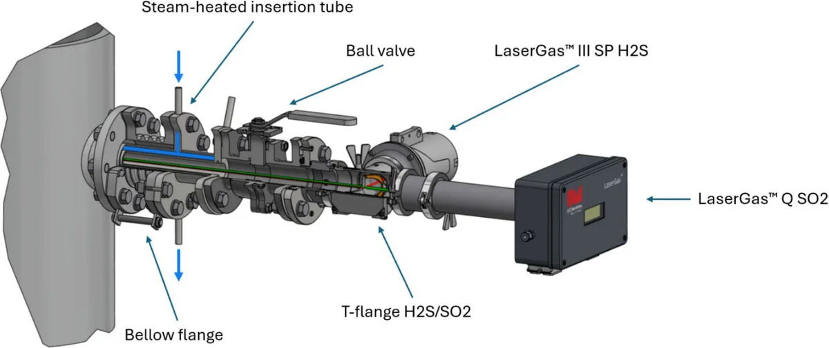
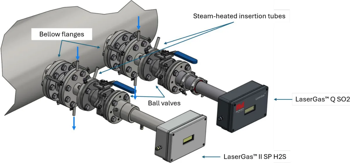
- Steam-heated insertion tubes keep the optical path above the sulphur dew point, so sulphur can’t deposit and block the laser beam. The steam circulates in a closed loop and never enters the process.
- Bellows flanges give flexible alignment of the analysers across the line.
- Ball valves at each mounting point let the analysers be removed safely for maintenance. They are closed during blowback to protect the analysers.
For particularly demanding duties, a blowback system can be added to clear deposits from the optical path.
Two ways to install
Combined T-flange. When a LaserGas III SP measures H₂S, a T-flange lets the H₂S and SO₂ analysers share a single pair of nozzles. This needs fewer nozzles and simplifies installation: one SRU installation kit and one T-flange.
Separate installation. Each analyser has its own pair of nozzles, so H₂S and SO₂ can be measured at different points. This needs two SRU installation kits.
The analyser versions and hardware depend on the line size, gas conditions and the nozzles available. Contact us with your SRU details and we’ll work out the configuration with NEO Monitors.
Source: NEO Monitors, In Situ Tail Gas Analysis in Sulfur Recovery Units (application note, 29 October 2026). Installation drawings courtesy of NEO Monitors. See the full set of instruments for the sulphur recovery unit.